Working on a replacement CPU board
Posted: 26 January 2014 Filed under: Electronics, General, Pinball Champ '82 | Tags: cpu, electronics, eprom, memory, zaccaria Leave a comment »
Well, here we go. I bought an old, untested CPU board on ebay quite a while ago. It clearly had some battery leakage problems that had been cleaned up by the previous owner, so now I need to fix the rest and get it up and running again.
Step 1: asses the damage.
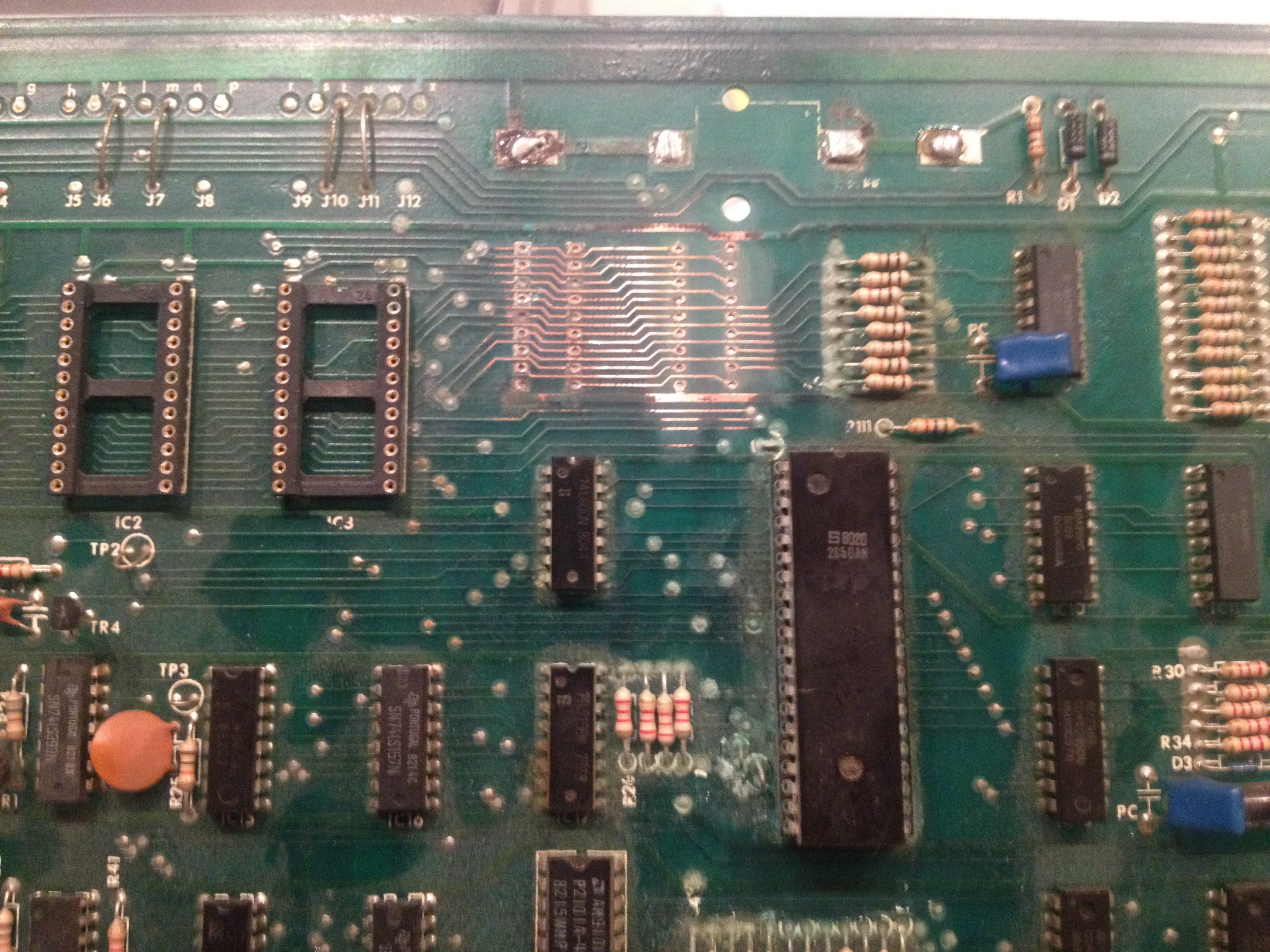
The CPU board when I received it
I noticed some of the copper was missing where the IC fittings used to be, so I first started with measuring the tracks that were still there. A lot of them are broken and not making the right connections. The breaks were too big to fix by covering them with a bit of solder on the component side of the PCB, so I will need to run wires on the solder side of the PCB. But first, I put in the missing IC fittings for the RAM chips.
Next I removed the 24-pin IC fittings for the three 2532 EPROMs. I replaced them with three 28-pin fittings so I can put in two 2764 EPROMs, which are needed to use David Gersic’s Freeplay ROMs and are much easier to come by. Using three fittings still gives me the option to put in the original 2532 EPROMs if needed. This also involves changing the jumpers just above the EPROM IC fittings.
As I am not going to reuse the IC fittings, I just cut them off.

Cutting away the old IC fittings.
The remaining “feet” were removed with a soldering iron. Once done, I just popped in the new 28-pin IC fittings and soldered them in place.

New fittings for the EPROMs and RAMs in place
All done.
Now I started measuring the connections on the new fittings and found that more than half were bad. This is going to be a lot of work. I’ve started wiring on the back side of the PCB, but time ran out, so I’m not finished yet. I have to redo connections between both RAM fittings and between the left RAM and right EPROM fittings. There was clearly a lot of damage from the battery leakage.

First two connections repaired, many to go…
I will keep you updated on my progress.
Upcoming projects
Posted: 7 January 2014 Filed under: Devil Riders, General, Pinball Champ '82 | Tags: cpu, display, driver board, electronics, pinball, zaccaria Leave a comment »
A new year, some new resolutions… Let’s get these machines finished.
The Pinball Champ’s displays are failing again, so I’m going to replace them with LEDs. The 7 segment displays are on order (estimated delivery 28 January), I have the PCB etching kit ready and I’m almost done with the PCB design (largely stolen from Leon).

Display PCB design
One of my pinball friends Eric exchanged my Pinball Champ backglass with a less damaged one. He only used his to hang on a wall in his gameroom and didn’t mind exchanging it for mine. One of the projects will be to fix the paint on the glass with some clear varnish. He also exchanged his Zaccaria etched playfield glass for my blank one, so now my Devil Riders also has an original playfield glass. Thanks again Eric!
Then finally I have scored myself a new 2nd generation CPU board. I’ve given up on the one I had for now, I might revisit it in the future, but it’s not very likely. The new CPU board has a bit of battery leakage damage around and under the memory chips that I need to fix. Hopefully I can get it to work 100% so I can put it in the Pinball Champ and get the Devil Riders’ CPU board back. Then I need to recheck all the electronics in the Devil Riders as my last CPU board test caused sparks on both the Power Supply and Driver board.
If all goes well both machines should be up and running by April 5th.
I’ll keep you posted.
The door to happiness
Posted: 19 December 2011 Filed under: Cabinet, Pinball Champ '82 | Tags: cleaning, coin door, pinball, zaccaria Leave a comment »
No, I’m not trying to sell you some guru meditation stuff. I just got my hands on a second hand coindoor for one of the machines and I’m happy with what I got at the price I got it!
The door was complete and in ok condition. Rather dirty, but then agian, why would that door be any different from the others.

A new door!
As you can see, someone had used paper stickers and electricians tape to cover the original plastic coin fronts. But otherwise, in very good shape.

Fully stocked
Except for the middle coin selector, everything is there. Dirty, but there.
First thing I did was take apart the front bezel and cleared away the paper stickers and electricians tape. Since there were three, I suspected they were the Deutsch Mark ones, like in the Pinball Champ. The Devil Riders has Belgian Frank ones and there are only two.

Uncovered and cleaned
To my surprise, these are Belgian Frank ones. With hindsight I should have known. The door is from a Time Machine and they came out when the 10 Fr piece was still in circulation. When Devil Riders came out, it wasn’t.

Cleaned and reassembled
The picture doesn’t do it justice. The chrome is damaged in two or three places, but it shines a lot. You can actually see my reflection in it.
At first my idea was to put this door in the Devil Riders, since some nitwit drilled a hole in the door to put a switch in to replace the outhole switch (I still get sick thinking of it). But then I decided to put it in the Pinball Champ. The frame looks a lot better and the door isn’t deformed, so it closes perfectly.
So after the usual dismantling, cleaning and reassembling, I installed it in the Pinball Champ and it looks great!

Installed and reproduction sticker attached
I added the reproduction sticker I got from David Gersic and now the Pinball Champ looks much better!
When the Devil Riders is finished, I’m going to set the coin selectors to 0.50 €, so if people really want to donate, they can.
In the mean time I also got that replacement coil for the popbumper in the Devil Riders and the part is back from the blacksmith waiting for reinstallation. That will be my next post.
More cleaning
Posted: 12 November 2011 Filed under: Devil Riders, Electronics, Mechanics, Pinball Champ '82, Playfield | Tags: cleaning, inserts, outhole kicker, pinball, playfield, popbumper, power supply, zaccaria Leave a comment »
I’ve received the new fuse clamps and quickly installed them on the Devil Riders’ power board. No more fiddling with the fuse.

New fuse clips installed
Then I took out the sunken inserts.

All sunken inserts removed
After a close inspection I saw that the 3000 hole is in the worst shape. It will need some wood filler and paint touch up.

This one is in the worst shape
I’ve reseated the inserts with some superglue, they shouldn’t move anymore.

Inserts reseated, still need to fill the wood and touch up the paint
I also took apart all the targets at the end of the playfield, cleaned them and reinstalled them. Fortunately, the print on them is still in good condition, so I don’t have to replace any of them.

Targets cleaned and adjusted
With that done, I started on the popbumpers. They were dirty and one is using a wrong coil that didn’t fit very well and was missing some screws.

Rebuilding the popbumper coil assembly

Rebuilding the popbumper
All the popbumpers are now clean and ready to be reinstalled. I kept the one with the wrong coil as I’m still looking for a replacement coil.
I also took apart the outhole kicker, cleaned it and reinstalled it. I noticed that the wrong coil used in the popbumper is the same coil that is used for the outhole kicker. So if I ever find a new popbumper coil, I’ll have a spare outhole kicker coil.

Outhole kicker cleaned and reinstalled
Next up the metal parts and the plastics. Then we can start to reassemble!
Oh and my dad came by for a game on the Pinball Champ…

Dad came by for a game on the Pinball Champ '82
Pinball Champ ’82 as good as done!
Posted: 6 November 2011 Filed under: General, Pinball Champ '82 | Tags: pinball, zaccaria Leave a comment »
It’s finished! The Pinball Champ ’82 has been put together again using the CPU board from the Devil Riders, using David’s freeplay images (see Zaccaria-Pinball in my links) and me and my dad played a few games. It was great!

My first pinball machine
Ofcourse during the games we played I noticed a few more things I need to fix, but nothing major. A light needs to be checked/replaced, the doorframe needs to be repainted and the backglass is missing a black siderail and could do with a new lift rail. Also, the player 2 display has one digit that acts up from time to time. I’ll have a look at that too.

The door
Unfortunately there’s a whole in the paint on the backglass just above a lamp. It’s quite an eye-sore. I’ll have to see if there’s a way to fix this…

Needs fixing...
The machine plays perfectly and I’m really happy with the result. Here’s a little movie with the machine in attract mode. Enjoy…
Driver boards tested and fixed
Posted: 1 November 2011 Filed under: Devil Riders, Electronics, Pinball Champ '82 | Tags: cpu, driver board, electronics, pinball, test program, tools, zaccaria Leave a comment »
So I put together the little address selector tool that Leon designed on his website (see my links) and used it to test both the Pinball Champ ’82 and Devil Riders driver boards.

Driver board test tool
I used a LED to test each input individually for the eight possible addresses.

Driver board test setup
I had to do it on the PC82 since I don’t have an independant 5V power supply anymore… really need to fix that!
The Devil Riders driver board was in perfect condition. This machine is turning out to be just a case of bad switches and dirt, lots of dirt… excellent!
The Pinball Champ driver board was another story. I had intermittend faults on connector CN21 while signal that came for the same SCR’s on CN18 where perfect. After a more thorough visual inspection of the board I noticed this:

Bad connector seating
As the solder didn’t appear broken and I had a very hard time desoldering this connector, I suspect it had been put together this way 29 years ago… So now it’s reseated properly and I replaced four SCR’s that were faulty, this board is now in tip-top shape as well.
I’ve also tested the Devil Riders CPU board with Leon’s test EPROM and it’s also in perfect condition. I’ve also found some discrepancies in the way the Pinball Champ CPU board functions compared to the Devil Riders board. I’ll get into that next as it’s the only thing that needs to be done before I can really get into the Devil Riders.
Wish me luck!
Humpty Dumpty back together again
Posted: 18 October 2011 Filed under: Cabinet, Pinball Champ '82, Playfield | Tags: cabinet, legs, neck, pinball, zaccaria Leave a comment »
It’s starting to look like a pinball machine agian!
I’ve put the playfield back together and noticed that the left top flipper didn’t work and the right top flipper was weak. A quick pass with some sanding paper between the leaf contacts and they’re both tiptop again.

Playfield completed
Here are some detail shots. Remember, I’m making this pinball playable, not perfect.

Playfield detail

Playfield detail

Playfield detail
Then I turned my attention to the neck. In my previous post I mentioned I was going to use a toothbrush to get the white spots in the black paint, but when I was at the store to get some more ground paint for the legs, I saw a black paint spray can that already had the white spots in it. It’s called “Granit” effect. So I bought a can and here is the result. I used one coat of black and one coat of the “Granit” black.

Neck

Neck detail

Neck detail
I like it!
Next where the legs. I got the two back legs back from the blacksmith and they were perfect (at a cost of an amazing 5€!). So I sanded them down, gave them a base coat, two coats of glossy black and new levelers (with rubber protectors).

Legs sanded

Legs primed
I also had a look at all the ground wires. NONE of them were connected in the transformer casing. That’s fixed now, my hair no longer reaches for the sky when I press the flipper buttons 😀
So I’m almost there, but not quite. The CPU board still needs work and the driver board still needs a thorough overhaul. In the mean time here’s a picture of where I am now.

The result so far.
Beheaded and dismembered
Posted: 13 October 2011 Filed under: Cabinet, Pinball Champ '82 | Tags: cabinet, cleaning, neck, painting, pinball, rust, zaccaria Leave a comment »
No, I didn’t kill the pinball machine! I just started some work on the neck and legs.

Beheaded and dismembered
So the legs have been taken off. The front legs are in good shape. The rusted levelers came out with some WD-40 and except for some rust the legs are fine. Sanding and painting up next. The back legs however are problematic. The rusted levelers are rusted in place and one leg is even bent at the bottom. I considered buying four new legs and levelers, but then I heard that there’s a blacksmith in our village. I should get those two back legs back tomorrow, straightened and levelerless (is that a word?). I’ve also ordered four new levelers.
I’ve also cleaned the head door. The ZM1550 display modules arrived today and these will be soldered in place after the weekend. So the door is ready to take the repaired displays. The guy who sold the modules to me added an extra display controller board which I will modify to take a LED display so it can run on 5V only and I can use it to test the CPU board without the 160V. I found this modification on Leon’s website (see my links for the flipper-pinball-fan site).
I’ve also ordered a new lock for the head and bought four M10 bolts and washers as the originals are missing. Unfortunately the bolts don’t seem to fit, I guess those Zaccarians used non-metric size bolts, I’ll have to check that.
Between the head and the cabinet, there is a neck with a little metal grill. This grill is completely rusted, so I beheaded the pinball machine and took the neck off.

The neck

Rusty
I immediately noticed a couple of things; first, one side of the neck was never painted and second the metal strip holding the cabinet glass was badly rusted.

Someone forgot to paint this side

Rusty
So I’ve removed everything from the neck and sanded it down for a new paintjob. I’m going to follow David Gersic’s advice (see his zaccaria-pinball site in my links section) on getting the white splatter back on the black paint using a tooth brush.
I’ve also cleaned up the metal strip using some steel wool and chrome polish. Nothing more, I want to play this machine, not put it in a museum.

Shiny
The metal grill has had it’s ground coat too.

Ground coat
The black paint you see under there is a remnant from painting the same style grill that resides at the bottom back side of the cabinet (nicely hidden). It came out perfect, so that’s why I’m doing this one in the same manner.
I’ve tried to paint the transformer casing with Hammerite paint, but that was a big mistake. Now it needs to harden for 2 weeks until I can sand it off again and start over.
Progress report
Posted: 1 October 2011 Filed under: Cabinet, Electronics, Pinball Champ '82, Playfield | Tags: cleaning, cpu, display, electronics, memory, pinball, playfield, test program, zaccaria, ZM1550 Leave a comment »
Well, the playfield is almost done!
I’ve cleaned out the cabinet and head.
I’ve installed the new microswitch (#52) that let’s the machine know the ball is on the 2nd level playfield.
I’m still missing a few rubbers, but they are in the mail.
The 20A fuse on the transformer box burned out while I was working on the playfield. I stuck a new one in and that burned out too. So I removed all the lights and measured the wiring to look for shorts. There were none. I stuck the lamps back in one by one and now everything works… Weird.
The guy I bought the ZM1550 display modules from mailed me to say he is abroad for work and will send them next week.
I still have the CPU board problem though… I’m going to swap out IC’s 8, 19, 31 and 37 for good measure. The way the CPU reacts to the DIP switch 4 position looks like it’s unable to read the settings once PROGR is off. When I put the switch back in PROGR mode, I can read all the settings, which to me means the RAM is good.
I’m also writing a extensive memory test program that will write alternative 0x55 and 0xAA’s to every memory position between 0x1800 and 0x1BFF. When a test fails it will show which test failed in which nibble at which location on the Player 1 display. This way I should be sure if the memory is good and I can test with both positions of DIP switch 4.
I’ll keep you updated.
Still debugging CPU problems…
Posted: 25 September 2011 Filed under: Electronics, Pinball Champ '82 | Tags: cpu, electronics, memory, pinball, test program, zaccaria Leave a comment »
As I stated in an earlier post, the pinball machine will only work when it is in PROGR mode (DIP switch 4 to ON position on the CPU board).
When the machine is in normal mode (DIP switch 4 to OFF position), al the displays show 0’s and that’s it. Sometimes not all displays will light up at once and it will take up to 30 seconds for all of them to turn on.
Lights on the head and playfield will stay on or off at random (changes every time I restart the machine).
When actuating the Test-Advance button in the door, it will go to test #1 and all the displays will test correctly showing 0’s, 1’s, 2’s, etc… up to 9’s and back to 0’s, but after that, there’s nothing I can do to stop that test, go to the next test or whatever.
Also, when I start the machine on normal mode, the error LED on the soundboard lights. Actually it always lights and never turns off. I noticed it takes a little time to turn off when the machine is turned on in PROGR mode, so I guess it’s the CPU not initialising the sound card.
I’ve tested the IC’s 31, 37, 19 and 8, but they all do what they’re supposed to do…

The PROGR circuit. The PROGR signal comes from DIP switch 4.
What you can see here is that the PROGR signal enables addresses 1C00 to 1C7F (or 1800 to 187F, since AB10 is not used but the software holds it high for RAM access) for writing when it is LOW. When the switch is put back to the OFF position, this memory range becomes read only.
So what’s next? I’m not really sure. There’s a few options:
- Maybe the TMS40L45-45NP is not a good substitute for the 2114L. I found some people who still have these, so I’ll get me one and see what happens.
- I write a test program than constantly writes to RAM when the CPU board LED is on and constantly reads from RAM when the CPU board LED is off and follow the R/W signal with my logic probe.
- Call Mulder and Scully to find the ghost in my machine…
Anyway, as always I’ll keep you updated.
 Videolan.org – The home of VLC