Working on a replacement CPU board
Posted: 26 January 2014 Filed under: Electronics, General, Pinball Champ '82 | Tags: cpu, electronics, eprom, memory, zaccaria Leave a comment »
Well, here we go. I bought an old, untested CPU board on ebay quite a while ago. It clearly had some battery leakage problems that had been cleaned up by the previous owner, so now I need to fix the rest and get it up and running again.
Step 1: asses the damage.
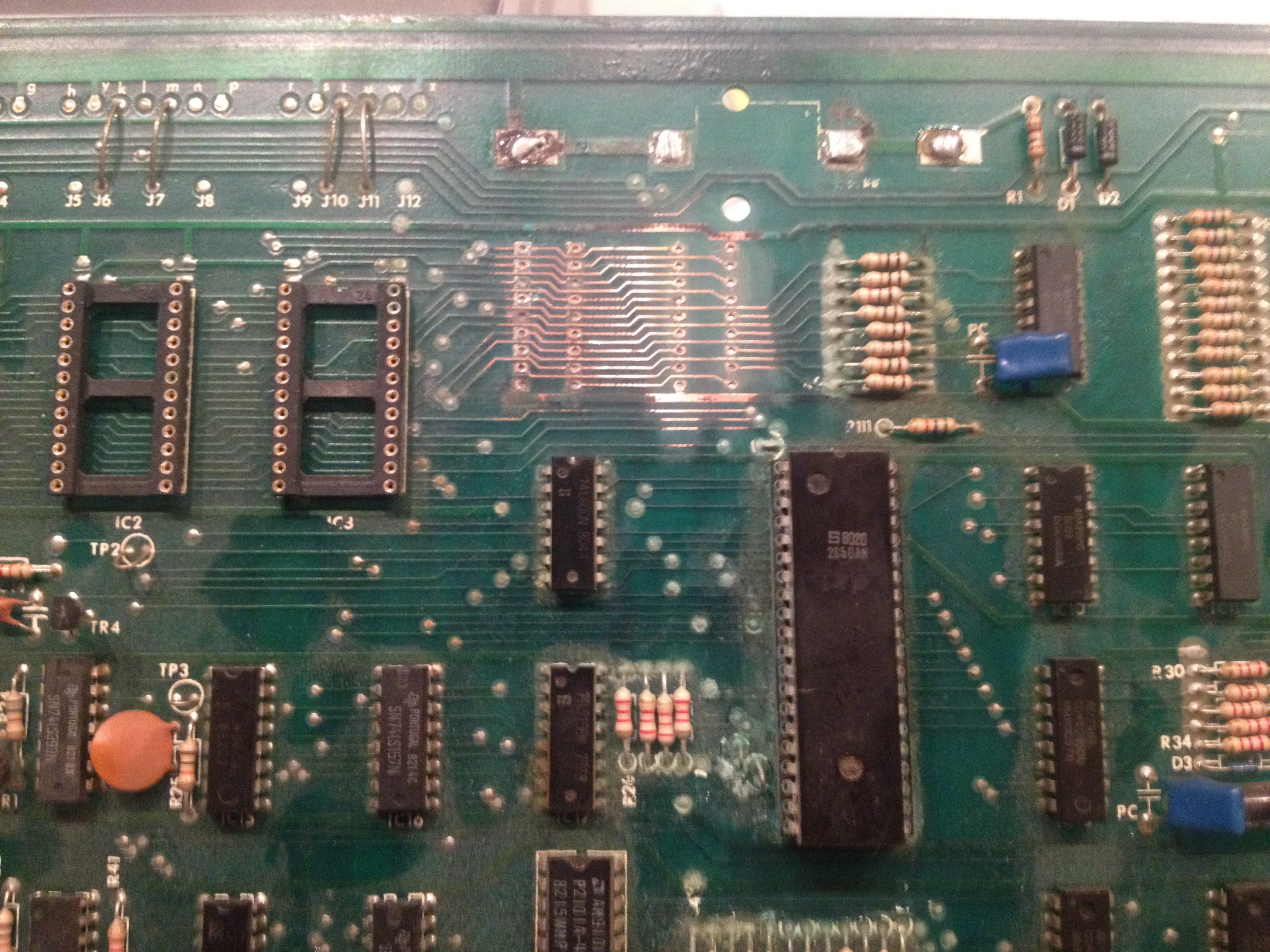
The CPU board when I received it
I noticed some of the copper was missing where the IC fittings used to be, so I first started with measuring the tracks that were still there. A lot of them are broken and not making the right connections. The breaks were too big to fix by covering them with a bit of solder on the component side of the PCB, so I will need to run wires on the solder side of the PCB. But first, I put in the missing IC fittings for the RAM chips.
Next I removed the 24-pin IC fittings for the three 2532 EPROMs. I replaced them with three 28-pin fittings so I can put in two 2764 EPROMs, which are needed to use David Gersic’s Freeplay ROMs and are much easier to come by. Using three fittings still gives me the option to put in the original 2532 EPROMs if needed. This also involves changing the jumpers just above the EPROM IC fittings.
As I am not going to reuse the IC fittings, I just cut them off.

Cutting away the old IC fittings.
The remaining “feet” were removed with a soldering iron. Once done, I just popped in the new 28-pin IC fittings and soldered them in place.

New fittings for the EPROMs and RAMs in place
All done.
Now I started measuring the connections on the new fittings and found that more than half were bad. This is going to be a lot of work. I’ve started wiring on the back side of the PCB, but time ran out, so I’m not finished yet. I have to redo connections between both RAM fittings and between the left RAM and right EPROM fittings. There was clearly a lot of damage from the battery leakage.

First two connections repaired, many to go…
I will keep you updated on my progress.
Progress report
Posted: 1 October 2011 Filed under: Cabinet, Electronics, Pinball Champ '82, Playfield | Tags: cleaning, cpu, display, electronics, memory, pinball, playfield, test program, zaccaria, ZM1550 Leave a comment »
Well, the playfield is almost done!
I’ve cleaned out the cabinet and head.
I’ve installed the new microswitch (#52) that let’s the machine know the ball is on the 2nd level playfield.
I’m still missing a few rubbers, but they are in the mail.
The 20A fuse on the transformer box burned out while I was working on the playfield. I stuck a new one in and that burned out too. So I removed all the lights and measured the wiring to look for shorts. There were none. I stuck the lamps back in one by one and now everything works… Weird.
The guy I bought the ZM1550 display modules from mailed me to say he is abroad for work and will send them next week.
I still have the CPU board problem though… I’m going to swap out IC’s 8, 19, 31 and 37 for good measure. The way the CPU reacts to the DIP switch 4 position looks like it’s unable to read the settings once PROGR is off. When I put the switch back in PROGR mode, I can read all the settings, which to me means the RAM is good.
I’m also writing a extensive memory test program that will write alternative 0x55 and 0xAA’s to every memory position between 0x1800 and 0x1BFF. When a test fails it will show which test failed in which nibble at which location on the Player 1 display. This way I should be sure if the memory is good and I can test with both positions of DIP switch 4.
I’ll keep you updated.
Still debugging CPU problems…
Posted: 25 September 2011 Filed under: Electronics, Pinball Champ '82 | Tags: cpu, electronics, memory, pinball, test program, zaccaria Leave a comment »
As I stated in an earlier post, the pinball machine will only work when it is in PROGR mode (DIP switch 4 to ON position on the CPU board).
When the machine is in normal mode (DIP switch 4 to OFF position), al the displays show 0’s and that’s it. Sometimes not all displays will light up at once and it will take up to 30 seconds for all of them to turn on.
Lights on the head and playfield will stay on or off at random (changes every time I restart the machine).
When actuating the Test-Advance button in the door, it will go to test #1 and all the displays will test correctly showing 0’s, 1’s, 2’s, etc… up to 9’s and back to 0’s, but after that, there’s nothing I can do to stop that test, go to the next test or whatever.
Also, when I start the machine on normal mode, the error LED on the soundboard lights. Actually it always lights and never turns off. I noticed it takes a little time to turn off when the machine is turned on in PROGR mode, so I guess it’s the CPU not initialising the sound card.
I’ve tested the IC’s 31, 37, 19 and 8, but they all do what they’re supposed to do…

The PROGR circuit. The PROGR signal comes from DIP switch 4.
What you can see here is that the PROGR signal enables addresses 1C00 to 1C7F (or 1800 to 187F, since AB10 is not used but the software holds it high for RAM access) for writing when it is LOW. When the switch is put back to the OFF position, this memory range becomes read only.
So what’s next? I’m not really sure. There’s a few options:
- Maybe the TMS40L45-45NP is not a good substitute for the 2114L. I found some people who still have these, so I’ll get me one and see what happens.
- I write a test program than constantly writes to RAM when the CPU board LED is on and constantly reads from RAM when the CPU board LED is off and follow the R/W signal with my logic probe.
- Call Mulder and Scully to find the ghost in my machine…
Anyway, as always I’ll keep you updated.
Memory check: passed!
Posted: 19 September 2011 Filed under: Electronics, Pinball Champ '82 | Tags: cpu, display, driver board, electronics, memory, pinball, zaccaria Leave a comment »
The mailman (actually a woman) had my new memory with her today! It took me all of 5 minutes to get the old 2114L out of the CPU board and the new 40L45 in. Popped Leon’s test EPROM back in and bingo, memory test passed!

The new 40L45 memory.
After that I did the input checks and I’m happy to say that that passed as well. So now all I need are the 3081 driver chips and probably a BC548 transistor (TR3) and the CPU board should be fixed fixed!

These two 3081’s are dead or heavily injured.

This little transistor is looking very suspicious indeed.
So I assembled everything except for the sound board and switched the machine on. There was life… sort of.

It’s alive!
I found the test button to be unresponsive, but when I put the CPU board in program mode using the dipswitch it did kind of start of normally. It was even able to kick the ball out of the out hole and the flippers, some bumpers and the poppers worked. But not much else. So the driver board needs work.

The flippers work.
Also, only two of the five 4×2-digit displays were fully functional, so 3 of them to check and fix.

Only two fully functional displays.
Still a lot of work ahead. To be continued…
Back home and back to work!
Posted: 18 September 2011 Filed under: Electronics, Pinball Champ '82 | Tags: cpu, display, electronics, eprom, memory, pinball, sound, test program, zaccaria Leave a comment »
Finally back from Sweden. There were quite a few packages waiting for me! Unfortunately, the TMS40L45 wasn’t one of them, so I couldn’t start work on the CPU board.
Or so I tought…
I started Leon’s test EPROM again and started testing all the outputs since I skipped over that test to find out if the memories where good. Well, I found two 3081 chips that are dead… that kind of explains why the LED on the soundboard always comes on when I attach it to the CPU board. So I’ve ordered a couple of those 3081’s and they should be here in a couple of days.
I also saw that all the signals on the CN14 connector for the displays were there, so I started fooling around with the idea of writing a little program to see if the displays still work. I guess I can’t wait for the CPU board to be fixed so I can use the built in tests. And it does keep me out of other trouble 😉
Anyway, I’m waiting for my EPROM to be erased to put the 3rd try on it. I have a good feeling this time… But then again, I had a good feeling every time.
If it works, I’ll let you know and post the program and some pictures.
Parts incoming!
Posted: 9 September 2011 Filed under: Electronics, General, Mechanics, Pinball Champ '82 | Tags: buy, cpu, electronics, mechanics, memory, pinball, zaccaria Leave a comment »
Although I’m in Sweden this week and the next, I haven’t forgotten about my pinball machine…
I’ve been franticly searching the Internet looking for those elusive parts that I so dearly need to get the machine back to pristine condition and I think I’ve done it.
From the Multigame site (see the links section) I’ve ordered a rubber set, a new pinball, a doorlock and some more small parts, together with some cleaning materials.
David, from www.zaccaria-pinball.com has sold me a spare “H” target and a replica door sticker and they are on the way.

David's spare "H"
And then the two memory chips… The 6514J-0 was relatively easy to find. A search on ebay found three vendors in the US, so I ordered one and it’s on the way. The 2114L was an alltogether different story. No hits on ebay or anywhere else.
It was even hard to find the correct datasheets for this memory chip, but after going through dozens of datasheets, I finally found the correct one. I’ve put it up here in the datasheets section on the right, so you don’t have to go through that experience yourself.
I found out that Texas Instruments made the same memory at different speeds, after looking up those datasheets and checking the TI speeds with the ones from Intersil, I started looking for a TMS2114L-45NL. Again, no luck 🙁
Then I noticed that the top of the Texas Instruments datasheets state “Previously Called TMS40L45”, so I searched for a TMS40L45-45NL on ebay and BINGO, there’s one on the way 🙂
According to the datasheets it should work, but I guess you never know until you put it in the CPU board and run the test.
Since I spend a lot of time looking for datasheets, I’ve decided to put them up here for anyone else that might be restoring a similar machine…
One step closer
Posted: 5 September 2011 Filed under: Electronics, Pinball Champ '82 | Tags: cpu, electronics, eprom, memory, pinball, zaccaria Leave a comment »
I finally managed to get my Willem EPROM programmer working in Windows 7 thanks to this article from Doug Brown. Thanks Doug! http://www.downtowndougbrown.com/2010/10/sivava-willem-eprom-programmer-on-windows-7-64-bit/
So after copying the original EPROM’s contents to my HDD (you never know!), I made a test EPROM on a 2532 chip as described on Leon’s Flipper-Fan site (see my links) and set up my test environment.

The test setup for the test with Leon's test EPROM
I ran the test a couple of times and found that the memory test fails every time!
So I need to replace the two memory chips, both ancient and hard to find…

One of these or both is defective.
I have already found a few online stores that sell the 6514J-9, but as for the 2114, no luck yet…
I’ll start by ordering the 6514J-9 and hope the 2114 still works. If not, I’ll need to look for a replacement.
Anyway, I’m in a hotel in Sweden for the next two weeks, doing some work, so there won’t be a lot of updates until I get back.
Cheers!
 Videolan.org – The home of VLC