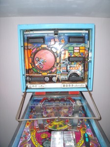
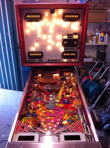
Upper playfield reinstalled and head door done.
Posted: 11 December 2011 Filed under: Devil Riders, Playfield | Tags: cleaning, neon tube, pinball, playfield, zaccaria Leave a comment »
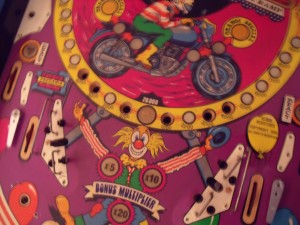
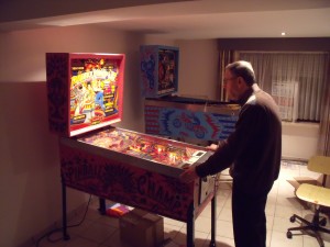
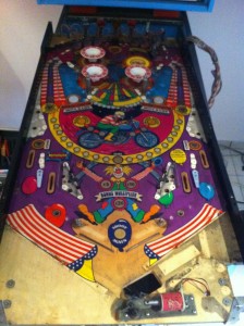
I finally got around to continuing the work on the Devil Riders. I finished the playfield as much as possible and disassembled the neon tube so I could get to the lamps in the backboard and clean everything up.
I’ve reinstalled the old flipperbats as the new ones are on backorder. Once they arrive, they will be installed. Unfortunately, I couldn’t find yellow flipper rubbers that are the right size, so I had to use black ones. If anyone knows where I can find yellow ones, please let me know.
Also, that metal part that was broken is still at the blacksmith, so the ball shooter lane hasn’t been put in yet.
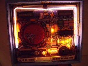
After that was done I started on the head door. I needed to get to the lights behind the plastic cover. For that I needed to remove the neon tube, but the rubbers isolating the connections are fused in place from 28 years of heating up and cooling down. I talked about it with Leon (flipper-pinball-fan) and David Gersic (Zaccaria-pinball) and they advised me to leave the rubbers and just undo the springs and put the neon on the playfield glass as carefully as possible.
Then I cut a slit on both sides of the plastic cover and took it off from around the neon tube leads. Worked like a charm and it’s impossible to see the slits now that the plastic cover is reinstalled.
When I checked out the neon more closely, I noticed some white spots on it. After close examination these where spots where the dirt had come loose… So I started cleaning the neon VERY carefully. The dirt, nicotine and tar didn’t come off very easily until I used one of those steel wool spunges used to clean cooking pots. The dust particles that came free from cleaning that way made me sneeze more than once.
I removed all the lightbulbs from the head door, tested them, cleaned and reinstalled the ones that still worked and replaced the faulty ones. The cover was cleaned too and reinstalled. Then I carefully put the neon back. The difference is huge, well worth the (little) effort and (considerable) risk.
Next up is a trip to the blacksmith and the CPU board.
Posts and rubber rings
Posted: 23 November 2011 Filed under: Devil Riders, Playfield | Tags: pinball, playfield, zaccaria Leave a comment »
Well, after all the metal works, I’ve moved on to the posts and rubber rings. Very straight forward. Install the posts, put the rings around them, move to the next location.
On thing I noticed, this time, is that I didn’t take enough pictures… I should have been more thourough in documenting as I disassembled the playfield, like I was with the Pinball Champ.
I also cleaned the posts as I needed them and not all at once like the previous time. I don’t think I gained time or effort by doing it this way, but it did break the monotomy and made the whole thing much more pleasant.
Here’s how I’ve gotten on today:
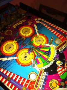
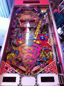
It’s starting to look like a pinball machine again! The only thing that is really going to be missing is the diverter that has the two broken off screw holes. I’m taking it to the blacksmith tomorrow to see if he can do something about that.
This is where most of the documentation was lacking; the top half… I’ve been looking at how many screws of what type are left and the holes in the plastics to see what goes where. So far so good. Should be able to get everything back together again tomorrow, except for the diverter and the shooter lane thingy.
The bottom half of the playfield did have enough pictures, so that was a straightforward build. Just waiting for the plastics and the retouch around the reseated inserts.
This is going to be an even better machine when it’s done that the Pinball Champ! Can’t wait!
Bad day at the office
Posted: 16 November 2011 Filed under: Devil Riders, Mechanics, Playfield | Tags: outhole kicker, pinball, playfield, popbumper, zaccaria Leave a comment »
Well, everything started off promisingly enough. I had already cleaned the popbumpers, so all I had to do was reinstall them. Or so I thought.
I had bought new mylar trim platters to replace the dirty and desintegrated old ones, so I started with cutting to of them to size. They need to have a corner cut out to fit around some posts that are really close to the bumper. Then I started installing the first popbumper. The base plate first, then the switch and then the popbumper body with the new mylar trim. Not good…
You can clearly see that the trim is lifted up about half a centimeter. Now way that’s right… So I dismantled the body again and had a close look at it all.
So the holes in the trim are too small. I should have noticed that earlier. I checked on the website of the place where I had bought them but since they only had one-size-fits-all, there’s nothing much I can do. So happy I just bought a new multi=tool!
So with a bit of finesse I managed to widen the hole and now the trim fits perfectly.
Rince and repeate three times and finally the popbumpers are installed.
That took a lot longer than expected and since I only had about 20 minutes left before I had to go, I thought to quickly install the new outhole switch. I soldered a diode over the appropriate contacts and went to get the bracket to fix it to the bottom of the playfield.
The bracket was no where to be found! Where did I put it. Where could it be. Then I remembered that I checked the bracket on the playfield to see which were the correct holes last time I worked it and I might have left it there when I left. And today while turning the playfield over to get tot the popbumpers it might have fallen off. After 5 minutes of sitting on my knees, clearing out my toolbox bit by bit, I still hadn’t found it. Finally I noticed something weird with one of the flipper assemblies, there was a piece of metal sticking out that shouldn’t be there. Sure enough it was the bracket that got lodged between the playfield and the flipper assembly. I had found it!
So I started screwing it in place only to notice one of the screws and bolts for the microswitch itself was missing. Where was it? Still on the old switch! So into the trashcan I went. Luckily I hadn’t emptied the trash yet, so it was still in there and I could recuperate the screw and bolt. With the new switch finally installed I soldered the leads to it and now the bottom part of the playfield is done.
So with all that bad luck and stupid mistakes, an hours worth of work took me over three hours to do. Bad day at the office indeed!
More cleaning
Posted: 12 November 2011 Filed under: Devil Riders, Electronics, Mechanics, Pinball Champ '82, Playfield | Tags: cleaning, inserts, outhole kicker, pinball, playfield, popbumper, power supply, zaccaria Leave a comment »
I’ve received the new fuse clamps and quickly installed them on the Devil Riders’ power board. No more fiddling with the fuse.
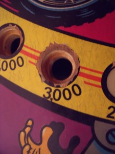
Then I took out the sunken inserts.
After a close inspection I saw that the 3000 hole is in the worst shape. It will need some wood filler and paint touch up.
I’ve reseated the inserts with some superglue, they shouldn’t move anymore.
I also took apart all the targets at the end of the playfield, cleaned them and reinstalled them. Fortunately, the print on them is still in good condition, so I don’t have to replace any of them.
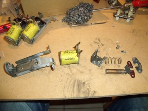
With that done, I started on the popbumpers. They were dirty and one is using a wrong coil that didn’t fit very well and was missing some screws.
All the popbumpers are now clean and ready to be reinstalled. I kept the one with the wrong coil as I’m still looking for a replacement coil.
I also took apart the outhole kicker, cleaned it and reinstalled it. I noticed that the wrong coil used in the popbumper is the same coil that is used for the outhole kicker. So if I ever find a new popbumper coil, I’ll have a spare outhole kicker coil.
Next up the metal parts and the plastics. Then we can start to reassemble!
Oh and my dad came by for a game on the Pinball Champ…
Playfield cleaning
Posted: 11 November 2011 Filed under: Devil Riders, Playfield | Tags: cleaning, pinball, playfield, popbumper, zaccaria 2 Comments »
While dismantling the playfield I noticed that the top flipper bats didn’t have their caps anymore and that the left bottom flipperbat had the cap glued on. I had to break it to get it off. Replacement bats have been ordered.
Also, the metal ramp at the end of the shooter lane is broken. It has a dent there where the ball hits it every time and the front screw holes are broken. I’m still looking for a replacement, let’s hope I find one.
So now I’m done removing everything from the playfield and boy, is it dirty!
The above picture still shows three of the four popbumbers installed, but they have been removed in the mean time and what I found is that one of them had the wrong coil in it and it was missing two screws that actually fixes it to the popbumber bracket…
So now the popbumbers have been removed and I was surprised that the mylar sheets under them aren’t just dirty, but some of them are even torn to pieces…
So now I started cleaning and the difference is amazing! Look at the yellow banner in the picture below, the right side has been cleaned, the left side hasn’t.
Now for the rest of the playfield, metal parts and plastics. Then I can start fixing the sunken inserts. That will be fun…
Humpty Dumpty back together again
Posted: 18 October 2011 Filed under: Cabinet, Pinball Champ '82, Playfield | Tags: cabinet, legs, neck, pinball, zaccaria Leave a comment »
It’s starting to look like a pinball machine agian!
I’ve put the playfield back together and noticed that the left top flipper didn’t work and the right top flipper was weak. A quick pass with some sanding paper between the leaf contacts and they’re both tiptop again.
Here are some detail shots. Remember, I’m making this pinball playable, not perfect.
Then I turned my attention to the neck. In my previous post I mentioned I was going to use a toothbrush to get the white spots in the black paint, but when I was at the store to get some more ground paint for the legs, I saw a black paint spray can that already had the white spots in it. It’s called “Granit” effect. So I bought a can and here is the result. I used one coat of black and one coat of the “Granit” black.
I like it!
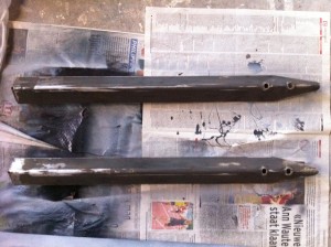
Next where the legs. I got the two back legs back from the blacksmith and they were perfect (at a cost of an amazing 5€!). So I sanded them down, gave them a base coat, two coats of glossy black and new levelers (with rubber protectors).
I also had a look at all the ground wires. NONE of them were connected in the transformer casing. That’s fixed now, my hair no longer reaches for the sky when I press the flipper buttons 😀
So I’m almost there, but not quite. The CPU board still needs work and the driver board still needs a thorough overhaul. In the mean time here’s a picture of where I am now.
Progress report
Posted: 1 October 2011 Filed under: Cabinet, Electronics, Pinball Champ '82, Playfield | Tags: cleaning, cpu, display, electronics, memory, pinball, playfield, test program, zaccaria, ZM1550 Leave a comment »
Well, the playfield is almost done!
I’ve cleaned out the cabinet and head.
I’ve installed the new microswitch (#52) that let’s the machine know the ball is on the 2nd level playfield.
I’m still missing a few rubbers, but they are in the mail.
The 20A fuse on the transformer box burned out while I was working on the playfield. I stuck a new one in and that burned out too. So I removed all the lights and measured the wiring to look for shorts. There were none. I stuck the lamps back in one by one and now everything works… Weird.
The guy I bought the ZM1550 display modules from mailed me to say he is abroad for work and will send them next week.
I still have the CPU board problem though… I’m going to swap out IC’s 8, 19, 31 and 37 for good measure. The way the CPU reacts to the DIP switch 4 position looks like it’s unable to read the settings once PROGR is off. When I put the switch back in PROGR mode, I can read all the settings, which to me means the RAM is good.
I’m also writing a extensive memory test program that will write alternative 0x55 and 0xAA’s to every memory position between 0x1800 and 0x1BFF. When a test fails it will show which test failed in which nibble at which location on the Player 1 display. This way I should be sure if the memory is good and I can test with both positions of DIP switch 4.
I’ll keep you updated.
Lamp socket field repair
Posted: 23 September 2011 Filed under: Electronics, How to's, Pinball Champ '82, Playfield | Tags: lamp socket, pinball, playfield, zaccaria Leave a comment »
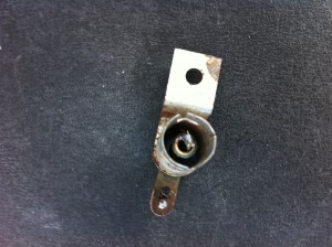
This is a little how to on how to “field”-repair a pinball lamp socket. With field repair I mean, you don’t have a new lamp socket handy and you want the thing working NOW. You don’t even have to disassemble the socket to do this, but for this tutorial I’m using pictures from a mounted and unmounted socket repair. This is a trick I learned when I was working as a technician in an arcade hall way back when…
So, your light doesn’t work, but there is power going to the socket. You test the socket and notice that there’s no connection between the “live” lip and the spring inside the socket. This is what you do:
With a piece of sanding paper, sand the top of the spring. Use your soldering iron to put a little dab of tin on the spring.
Take an end of shielded wire and strip one end about half a centimeter. Bend the exposed wire in a little hook and put a bit of tin on it with you soldering iron.
Thread the shielded part through the spring and make sure the hook catches on the spring.
Solder it thight, easy job since the tin is already on the metal. Just heat it up.
Then cut the wire to length, strip the end and solder it to the “live”-lip.
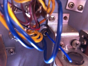
If you’re working on a mounted socket, be sure that you don’t unsolder the other wires.
Now pop in the lamp and if you followed this guide correctly…
Now get to work!



















 Flippers.be
 Videolan.org – The home of VLC