Driver boards tested and fixed
Posted: 1 November 2011 Filed under: Devil Riders, Electronics, Pinball Champ '82 | Tags: cpu, driver board, electronics, pinball, test program, tools, zaccaria Leave a comment »
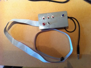
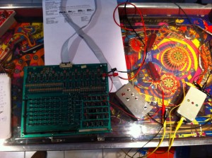
So I put together the little address selector tool that Leon designed on his website (see my links) and used it to test both the Pinball Champ ’82 and Devil Riders driver boards.
I used a LED to test each input individually for the eight possible addresses.
I had to do it on the PC82 since I don’t have an independant 5V power supply anymore… really need to fix that!
The Devil Riders driver board was in perfect condition. This machine is turning out to be just a case of bad switches and dirt, lots of dirt… excellent!
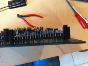
The Pinball Champ driver board was another story. I had intermittend faults on connector CN21 while signal that came for the same SCR’s on CN18 where perfect. After a more thorough visual inspection of the board I noticed this:
As the solder didn’t appear broken and I had a very hard time desoldering this connector, I suspect it had been put together this way 29 years ago… So now it’s reseated properly and I replaced four SCR’s that were faulty, this board is now in tip-top shape as well.
I’ve also tested the Devil Riders CPU board with Leon’s test EPROM and it’s also in perfect condition. I’ve also found some discrepancies in the way the Pinball Champ CPU board functions compared to the Devil Riders board. I’ll get into that next as it’s the only thing that needs to be done before I can really get into the Devil Riders.
Wish me luck!
ZM1550 test setup
Posted: 27 October 2011 Filed under: Electronics, General | Tags: display, tools, ZM1550 3 Comments »
I’ve been lucky and was able to buy 27 used, untested ZM1550’s. So I’ve made a test setup to get them all sorted out as fast as possible once they arrive.
This is just a little test print on which I soldered three 5 pin connectors and one 4 pin connector and then connect all the segments of both digits together (a with a, b with b, etc.). Then I soldered some wires to connect them to the CN3 connector on the pinball display driver. The shield is connected to pin 1 of CN1 and the decimal points and both anodes are connected to the appropriate pins on CN2 in the same way.
Fortunately, the first ZM1550 module I put in worked, so I know the setup was good.
Unfortunately, not all the modules I put in worked 🙁
Which tools do I use?
Posted: 30 August 2011 Filed under: Electronics, General | Tags: eprom, logic probe, pinball, tools Leave a comment »
Well, so far it’s quite straightforward… a digital multimeter (I use the Velleman DVM-4100), a 30W soldering iron and a whole range of screwdrivers and pliers.
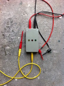
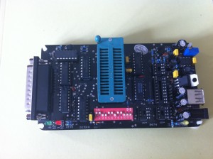
In preparation of repairing the CPU board, I have bought a Willem EPROM programmer (off ebay), two 2532 EPROMS (oh yes, I found some) and made a logic probe as described on the flipper-pinball-fan website (see my links).
Now I’m waiting for a PCMCIA Parallel port card for my laptop, so I can connect the EPROM programmer and make me a copy of Leon’s test EPROM from the flipper-pinball-fan website (see my links). Then the testing will continue!


 Flippers.be
 Videolan.org – The home of VLC