Upcoming projects
Posted: 7 January 2014 Filed under: Devil Riders, General, Pinball Champ '82 | Tags: cpu, display, driver board, electronics, pinball, zaccaria Leave a comment »
A new year, some new resolutions… Let’s get these machines finished.
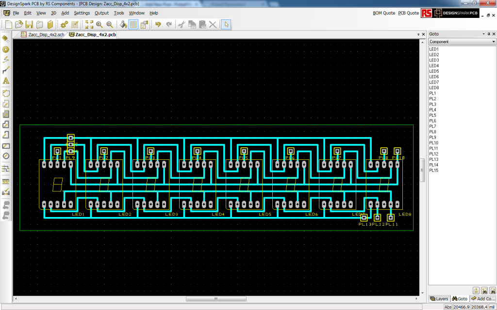
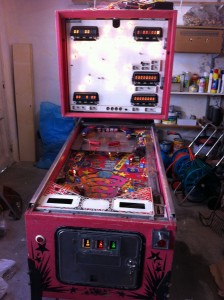
The Pinball Champ’s displays are failing again, so I’m going to replace them with LEDs. The 7 segment displays are on order (estimated delivery 28 January), I have the PCB etching kit ready and I’m almost done with the PCB design (largely stolen from Leon).
One of my pinball friends Eric exchanged my Pinball Champ backglass with a less damaged one. He only used his to hang on a wall in his gameroom and didn’t mind exchanging it for mine. One of the projects will be to fix the paint on the glass with some clear varnish. He also exchanged his Zaccaria etched playfield glass for my blank one, so now my Devil Riders also has an original playfield glass. Thanks again Eric!
Then finally I have scored myself a new 2nd generation CPU board. I’ve given up on the one I had for now, I might revisit it in the future, but it’s not very likely. The new CPU board has a bit of battery leakage damage around and under the memory chips that I need to fix. Hopefully I can get it to work 100% so I can put it in the Pinball Champ and get the Devil Riders’ CPU board back. Then I need to recheck all the electronics in the Devil Riders as my last CPU board test caused sparks on both the Power Supply and Driver board.
If all goes well both machines should be up and running by April 5th.
I’ll keep you posted.
ZM1550 test setup
Posted: 27 October 2011 Filed under: Electronics, General | Tags: display, tools, ZM1550 3 Comments »
I’ve been lucky and was able to buy 27 used, untested ZM1550’s. So I’ve made a test setup to get them all sorted out as fast as possible once they arrive.
This is just a little test print on which I soldered three 5 pin connectors and one 4 pin connector and then connect all the segments of both digits together (a with a, b with b, etc.). Then I soldered some wires to connect them to the CN3 connector on the pinball display driver. The shield is connected to pin 1 of CN1 and the decimal points and both anodes are connected to the appropriate pins on CN2 in the same way.
Fortunately, the first ZM1550 module I put in worked, so I know the setup was good.
Unfortunately, not all the modules I put in worked 🙁
Progress report
Posted: 1 October 2011 Filed under: Cabinet, Electronics, Pinball Champ '82, Playfield | Tags: cleaning, cpu, display, electronics, memory, pinball, playfield, test program, zaccaria, ZM1550 Leave a comment »
Well, the playfield is almost done!
I’ve cleaned out the cabinet and head.
I’ve installed the new microswitch (#52) that let’s the machine know the ball is on the 2nd level playfield.
I’m still missing a few rubbers, but they are in the mail.
The 20A fuse on the transformer box burned out while I was working on the playfield. I stuck a new one in and that burned out too. So I removed all the lights and measured the wiring to look for shorts. There were none. I stuck the lamps back in one by one and now everything works… Weird.
The guy I bought the ZM1550 display modules from mailed me to say he is abroad for work and will send them next week.
I still have the CPU board problem though… I’m going to swap out IC’s 8, 19, 31 and 37 for good measure. The way the CPU reacts to the DIP switch 4 position looks like it’s unable to read the settings once PROGR is off. When I put the switch back in PROGR mode, I can read all the settings, which to me means the RAM is good.
I’m also writing a extensive memory test program that will write alternative 0x55 and 0xAA’s to every memory position between 0x1800 and 0x1BFF. When a test fails it will show which test failed in which nibble at which location on the Player 1 display. This way I should be sure if the memory is good and I can test with both positions of DIP switch 4.
I’ll keep you updated.
All electronics fixed, but still problems…
Posted: 23 September 2011 Filed under: Electronics, Pinball Champ '82 | Tags: cpu, display, electronics, pinball, sound, test program, zaccaria, ZM1550 Leave a comment »
The mailwoman came with goodies this morning; four 3081 chips! So I put them in the CPU board and ran Leon’s test EPROM again. Victory!
So I mounted the board back into the pinball machine, connected everything and switched it on. Not so good… The sound was weird, only a few cracks and screeches would come out of the speaker.
I disconnected the sound board from the CPU board and ran the test and all went well, so clearly there was a problem with the communication between the CPU board and the sound board. I checked the schematics and the only thing that could be wrong was the entry stage behind CN7.
Using my multimeter I immediately found that all the data lines where shorted to the +5V. So only the resistor array ICR6 or the 74LS244 could be the cause. So I started with desoldering the resistor array, but that wasn’t the problem. So I desoldered the 244 and found the culprit!
Off to the store I went. Bought a couple of BF422’s and a 4042 as well for the two display driver boards that needed them and even went round to the hardware store to get some screws, there’s a lot of screws missing in the cabinet and head.
Back home, I put all the components where they should be and succes! I have sound!
The two display driver boards got their components too and now I have 4 working displays.
Next week my ZM1550’s should arive and then I can fix the last display.
And that’s it for the electronics… OR IS IT???
The game still won’t start. No flickering lights, no sound, no highscore showing, nothing… just all 0’s on the displays and that’s it.
When I put DIP switch 4 in PRGM mode, the soundboard now makes the annoying warning sound and I can do all the tests, reset the accounting and set all the options. So I set the options, resetting the ones that already had a good value, clear the accounting and do the tests. All tests are fine. The displays do their thing, the lights go on and off, the solenoids scare me and the sounds are played in order. But then there’s the button test (test #2) that just shows 18. And whatever button I press, it doesn’t change. I guess I’ll have to go through the wire harness and measure what signals I do get.
Guess that’s my queue to end this article and get back to work!
Displays, displays, displays…
Posted: 21 September 2011 Filed under: Electronics, Pinball Champ '82 | Tags: display, electronics, pinball, zaccaria, ZM1550 Leave a comment »
Guess what I’ve been doing yesterday… correct! Fixing displays…
As you might remember from a previous post, I had two working displays and three that needed work.
Well, after a days work, I have three working displays, and components ordered to make that five (5) working displays!
I had three 4×2 digit display boards with faulty ZM modules. So after some soldering magic, I now have two more working 4×2 digit display boards and one with two (possibly three) faulty ZM modules. Luckily I found a fellow enthousiast who has a few Valvo ZM1550 modules to spare, so there should be four of them coming my way soon! YAY!
Three of the display driver boards were faulty. After some testing, I found one board with a faulty IC2 (4042) and two boards with a faulty BF422’s. From the two boards with the faulty BF422’s, I made one working one. With the BF422 transistors and the 4042 chip on order, the display driver boards should be ready.
Pinball life is good!
Memory check: passed!
Posted: 19 September 2011 Filed under: Electronics, Pinball Champ '82 | Tags: cpu, display, driver board, electronics, memory, pinball, zaccaria Leave a comment »
The mailman (actually a woman) had my new memory with her today! It took me all of 5 minutes to get the old 2114L out of the CPU board and the new 40L45 in. Popped Leon’s test EPROM back in and bingo, memory test passed!
After that I did the input checks and I’m happy to say that that passed as well. So now all I need are the 3081 driver chips and probably a BC548 transistor (TR3) and the CPU board should be fixed fixed!
So I assembled everything except for the sound board and switched the machine on. There was life… sort of.
I found the test button to be unresponsive, but when I put the CPU board in program mode using the dipswitch it did kind of start of normally. It was even able to kick the ball out of the out hole and the flippers, some bumpers and the poppers worked. But not much else. So the driver board needs work.
Also, only two of the five 4×2-digit displays were fully functional, so 3 of them to check and fix.
Still a lot of work ahead. To be continued…
Back home and back to work!
Posted: 18 September 2011 Filed under: Electronics, Pinball Champ '82 | Tags: cpu, display, electronics, eprom, memory, pinball, sound, test program, zaccaria Leave a comment »
Finally back from Sweden. There were quite a few packages waiting for me! Unfortunately, the TMS40L45 wasn’t one of them, so I couldn’t start work on the CPU board.
Or so I tought…
I started Leon’s test EPROM again and started testing all the outputs since I skipped over that test to find out if the memories where good. Well, I found two 3081 chips that are dead… that kind of explains why the LED on the soundboard always comes on when I attach it to the CPU board. So I’ve ordered a couple of those 3081’s and they should be here in a couple of days.
I also saw that all the signals on the CN14 connector for the displays were there, so I started fooling around with the idea of writing a little program to see if the displays still work. I guess I can’t wait for the CPU board to be fixed so I can use the built in tests. And it does keep me out of other trouble 😉
Anyway, I’m waiting for my EPROM to be erased to put the 3rd try on it. I have a good feeling this time… But then again, I had a good feeling every time.
If it works, I’ll let you know and post the program and some pictures.







 Flippers.be
 Videolan.org – The home of VLC